Interface the HX711 to Pi
Building a Raspberry based electronic scale using the DCT Electronic HX711 board is as easy as Pi!
NOTE: THIS PAGE IS OBSOLETE.
For historical and reference use only.
We now use different hardware, software and calibration formulas.
Contents
Required Parts
There are several HX711 boards available. They usually come with two sets of male headers: straight and right angle.
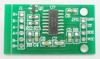
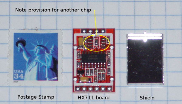
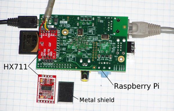
We have been testing the brown boards that include a metal shield. There are two versions of those available. Some only have one chip, some have two.
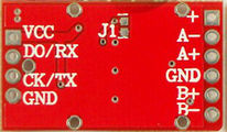
Different HX711 boards call the digital communication signals by different names and arrange them in different orders.
| P1/J8 | Pi | Brown HX711 | Green HX711 |
|---|---|---|---|
| Pin 2 | +5 | Vcc | Vcc |
| Pin 16 | GPIO28 | DO/RX | DT |
| Pin 18 | GPIO30 | CK/TX | SCK |
| Pin 20 | Ground | GND | GND |
Installation
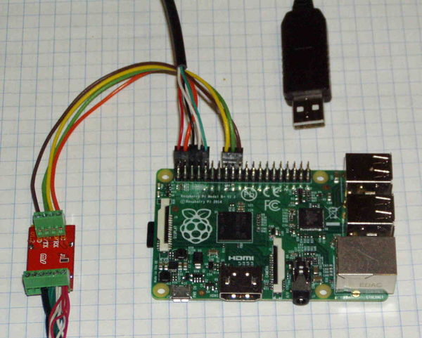
Method 1: Connect HX711 to P1/J8
This will work with all models of the Pi: A, B, A+, B+.
Prepare the HX711 board
First prepare the HX711 board by soldering the shield and connectors.
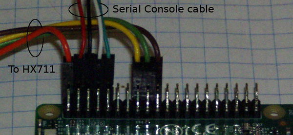
Pins 2, 16, 18, 20 on P1 (Model A and B) or J8 (Model A+ and B+) are used:
| P1/J8 | Pi | HX711 | Color |
|---|---|---|---|
| Pin 2 | +5 | Vcc | Red |
| Pin 16 | GPIO28 | DO/RX | White |
| Pin 18 | GPIO30 | CK/TX | Green |
| Pin 20 | Ground | GND | Black |
Change the GPIO pins in hx711.c from 30 and 31 to 23 and 24.
#define CLOCK_PIN 24
#define DATA_PIN 23
Method 2: Connect HX711 to P5
This will only work on the Model A and B (not on the A+ nor B+ as they don't have P5).
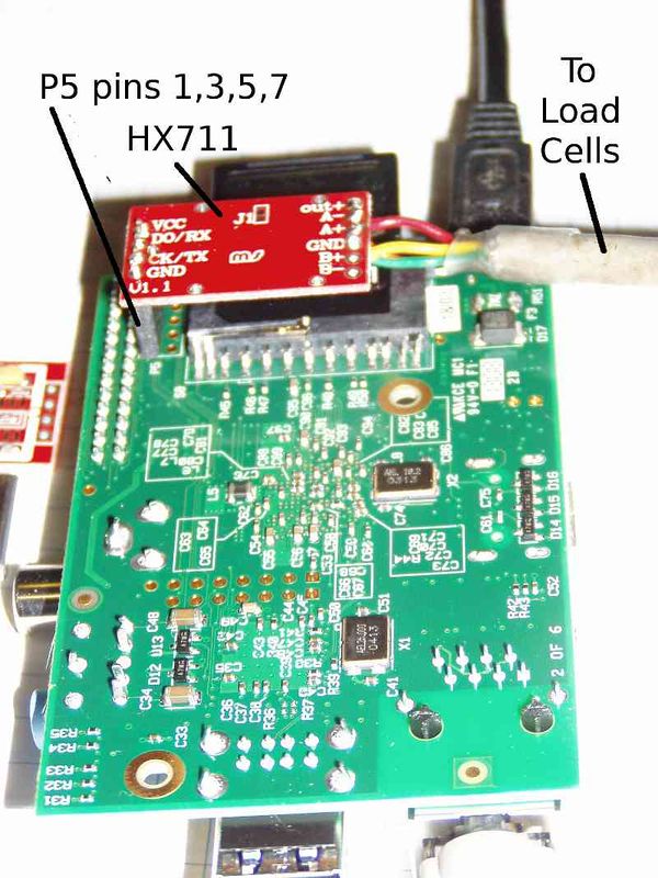
You will need a 1x4 female header (2.54mm Pitch Straight Single Row PCB Female Pin Headers) and load cells.
- Order the board for $6.99 on Ebay
This one for $2.17 should work, too. - Download the software from gitHub
git clone https://github.com/ggurov/hx711 - Solder a 1x4 straight female header in P5 on Pi (bottom side of board) and a 1x4 male header on the DCT board
- Solder the load cells to the DCT board.
- Plug the DTC board into the Pi.
- Change the GPIO pins in hx711.c from 30 and 31 to 28 and 30. This way they are all on one side of P5:
| P5 | Pi | HX711 |
|---|---|---|
| P5-1 | +5 | Vcc |
| P5-3 | GPIO28 | DO/RX |
| P5-5 | GPIO30 | CK/TX |
| P5-7 | Ground | GND |
#define CLOCK_PIN       30
#define DATA_PIN        28
Testing
There is a README file with the HX711 software. After the HX711 software is installed run the hx711 program with no arguments:
sudo hx711
It will spit out 64 lines and after the last line, there will be a number (in this case 146640):
0 0 0 0 0 0 0 0 0 0 0 0 1 0 1 1 1 1 0 0 1 1 0 0 1 1 0 0 1 0 1 1 n:    1546646     -
0 0 0 0 0 0 0 0 0 0 0 0 1 0 1 1 1 1 0 0 1 1 0 1 0 0 0 1 0 1 0 1 n:    1546794     -
0 0 0 0 0 0 0 0 0 0 0 0 1 0 1 1 1 1 0 0 1 1 0 1 1 0 1 0 1 0 0 0 n:    1547088     -
0 0 0 0 0 0 0 0 0 0 0 0 1 0 1 1 1 1 0 0 1 0 1 1 1 1 0 1 1 1 0 0 n:    1546168     -
0 0 0 0 0 0 0 0 0 0 0 0 1 0 1 1 1 1 0 0 1 0 1 1 1 1 0 0 0 0 1 1 n:    1546118     -
0 0 0 0 0 0 0 0 0 0 0 0 1 0 1 1 1 1 0 0 1 0 1 1 1 0 0 0 1 1 1 1 n:    1546014     -
1546640
The numbers you get will be totally different (this was run with a 57 lb hive on the load cells)
The last number 1546640 is the average of the 64 reads. The numbers may be negative. That is OK.
You should be able to put some weight on the load cells, run hx711 again and the numbers should be different.
Calibration
A linear transformation is used to convert the ADC output (counts) to lbs or Kgs: Y=mX+b where
- Y is pounds or kilograms
- m is the slope
- X is the ADC output
- and b is the intercept.
Calibration consists of determining the zero value (intercept) and then the slope.
The hx711 program will subtract the zero ( b is negative) for you.
- With the load cells mounted in some kind of frame and possibly with a bottom board attached, run hx711. Remember the last number it displays. You may wish to run hx711 several time to make sure it is stable.
- Now run hx711 with that number as an argument:
$ sudo hx711 1546640
Your number will be different. It will depend on the load cells and the load that you are calling zero.
There will be a short delay. This time it will not output the 64 lines, just the average. The average should be small, close to zero. There will be some noise, but it should be a relatively small number. (Remember this is a 24 bit A to D converter. 2 to the 24th power is 16,777,216 so a "small" number may be several hundred.)
- Now put a known weight on the frame. It could be a 5 lb bag of sugar. The bigger, the better. I usually weigh myself, then step on the frame and run hx711.
I use a small delay like ten seconds (sleep 10) to give me time to step on the frame:
$ sudo sleep 10; hx711 12345
Note that the number you pass to the hx711 program (here 12345) will be different and will be the number you determined in the previous step as the zero reading.
All that remains is to determine the slope. I use the inverse of the slope ( 1/slope) but the method is the same.
Determine counts per pound by dividing the number returned in the previous step by the weight. For example,
If the output was 3,088,500 with 150 lbs on the scale, divide 3,088,500 by 150. In this case 1/slope would be 20590 counts per pound.
So, to summarize:
- determine the zero reading
- Run hx711 with the zero reading as an argument
- Divide the output by 1/slope
- That should be the weight in pounds.
I run this short bash script during testing. It will read the scale and output the weight every 5 seconds. Note that the utility bc (binary calculator) must be installed.
while [ 1 ]
do
DATE=`date`
echo $DATE
COUNTS=`timeout 5 ./hx711 23000`
echo $COUNTS
WEIGHT=`echo "scale=2; ($COUNTS/20550)" | bc`
echo -e "$WEIGHT\n\r"
sleep 5
done
You will have to change the zero and the 1/slope to the numbers you measured. Edit the file:
- change 23000 in line 5 to your zero
- change 20550 in line 7 to the the number you calculated as 1/slope
Copy this code to a file like scale_test and make it executable:
sudo chmod a+x scale_test
then run it
sudo ./scale_test
Temperature Compensation
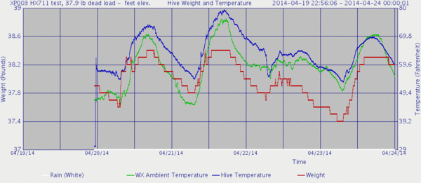
Temperature Sensitivity
From the CZL635 Spec Sheet link below:
Temperature Effect on Span 2.5 g/°C
Temperature Effect on Zero 5 g/°C
From the CZL602X Spec Sheet link below:
Temperature Effect on Span 0.02%F.S/10℃
Temperature Effect on Zero 0.03%F.S/10℃
Full Scale = 50 kg

.02% F.S/10℃
.0002 * 50 kg = .01 kg / 10℃
              = .001 kg / 1℃
              = 1 g/ 1℃
So the CZL602X are 2.5 times more stable than the CZL635
HX711 Spec Sheets
http://hivetool.org/w/images/d/d2/Hx711_english.pdf
