Hardware: Legacy HX711 wiring
Contents
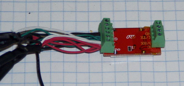
Solder shield and terminal block connectors on HX711 board.
This is already done on the developer kits, This step is only necessary if you obtain parts independently.
Solder shield and connectors on HX711 board.
Assemble Electronics
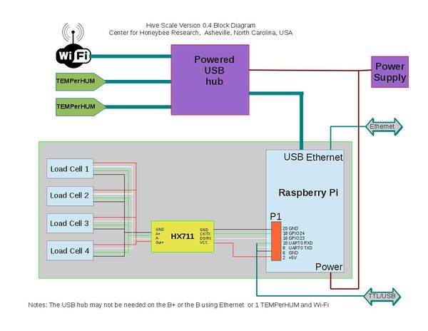
The electrical connections are made as shown on the block diagram.
A USB hub may not be necessary if using the B+ (it has 4 USB ports) or if the DHT series of temperature/humidity sensors are used (they connect to the P1/J8 header).
There are several different ways to power the Pi.
Connect load cells.
- Each load cell has five wires:
| Color | HX711 |
|---|---|
| Red | Vout |
| White | A- |
| Green | A+ |
| Black | Ground |
| Black w/ small white writing | Shield |
Do not cut or extend these wires for best performance. These load cells are a matched set. If you are building more than one scale, do not mix the load cells from different Dev Kits. They were custom manufactured with 1 meter shielded cables.
The four load cells are connected in parallel (the four red wires are connected together, the four white wires are connected together, etc.) It is important to note that there is a difference between the two black wires. The black wire that is connected to Ground is solid black and it is the same shape (round) as the red, white, and green wires. The black wire with small white writing on it with the end "smashed" is connected to Shield.
It may be difficult to read the labels on the HX711 because of how the terminal was soldered onto the board. Start with connecting the red wire and work your way to the black w/ small white lettering. Use caution to ensure that the bare wires do not contact each other. There are a lot of wires to pack into the terminals and it may take some patience.
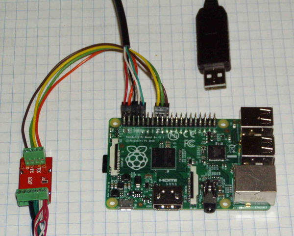
Connect HX711 serial I/O and power to Pi.
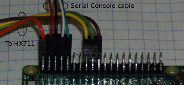
Pins 2, 16, 18, 20 on P1 (Model A and B) or J8 (Model A+ and B+)are used:
| P1/J8 | Pi | HX711 | Color |
|---|---|---|---|
| Pin 2 | +5 | Vcc | Red |
| Pin 16 | GPIO28 | DO/RX | White |
| Pin 18 | GPIO30 | CK/TX | Green |
| Pin 20 | Ground | GND | Black |
Connect USB/Serial Console cable to Pi
A USB/Serial cable is not required but may be necessary to configure the Pi if it doesn't have an Ethernet port. This cable allows logging into the console (terminal) command line interface. It also can be used to power the Pi when testing.
*If the Pi will be powered from another source, do not connect the red wire (+5) to Pin 4. Leave it unconnected.
Pins 4, 6, 8, 10 on P1/J8 are used:
| P1/J8 | Pi | Color |
|---|---|---|
| Pin 4 | +5* | Red |
| Pin 6 | Ground | Black |
| Pin 8 | TxD | White` |
| Pin 10 | RxD | Green |
Connect Hub, WiFi, and TEMPerHUMs
- A USB hub may not be necessary if using the B+ (it has 4 USB ports) or if the DHT series of temperature/humidity sensors are used (they connect to the P1/J8 header).
- A powered USB hub provides an inexpensive way to power the system. See Powering the Pi section below.
- Using the cable provided with the hub, connect one of the USB ports on the Pi to the input port on the HUB.
- Using a Type B USB to Micro B USB cable, connect one of the hub's USB ports to the Pi's power connector.
- Plug the power supply provided with the hub into the HUB voltage input.
- Plug the USB sensors into the hub.
Note: For initial testing the the TEMPerHUM sensors and WiFi adapter may be plugged directly into the hub.
However, the heat from the hub will affect the temperature reading.  It is necessary to  isolate the
TEMPerHUMs from the heat with USB extension cables.
- If using WiFi, plug the WiFi adapter into a USB port.
- Make a backup copy of ifupdown in the /etc/ifplugd/action.d/ directory
- Copy the ifupdown file that comes with WPA_suplicant to /etc/ifplugd/action.d/
- Reboot
- If using Ethernet, plug the Ethernet cable from the router into the Pi (only available on the B and B+ models.)
An extension cable may be necessary to locate the WiFi adapter where it has good reception.
Automatically Reconnect WiFi[1]
sudo mv /etc/ifplugd/action.d/ifupdown /etc/ifplugd/action.d/ifupdown.orig
sudo cp /etc/wpa_supplicant/ifupdown.sh ./ifupdown
sudo reboot


