Hardware: Sensor Wiring
The Developers Kit Raspberry Pi Hive Interface Board uses modular telephone RJ14 (6P4C) connectors for the sensors. Pins 2, 3, 4, and 5 are used.
Eventually, the load cells will be supplied with the connector attached. Cables will be provided for the other sensors.
These instructions are for developers that use the Dev Kit Raspberry Pi Hive Interface board versions 0.1 or 0.2.
The Registered Jack (RJ) series connectors install using an inexpensive crimping tool.
Contents
RJ Connectors
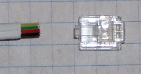
Crimp on Registered Jack (RJ) plugs are insulation displacement connectors (IDC) that pierce the insulation on the wire, forming a gas tight joint. Some RJ connectors are designed to take round cable, some flat, some both. Some are designed for solid wire, some for stranded, some for both.
The male connectors are called plugs. The female connectors are called jacks. They are designated by the number of positions (P) and the number of contacts (C) that are populated. We are currently using 6P4C (six position, four contact) plugs and jacks.
For a detail description, see Registered Jack on Wikipedia.
Number of Contacts
Contact numbering
Load Cells
| Load Cell Wiring | |||
|---|---|---|---|
| RJ14 Pin | Color | HX711 | Description |
| 2 | Red | Out+ | Excitation voltage from HX711 voltage regulator |
| 3 | White | A+ | A/D positive input |
| 4 | Green | A- | A/D negative input |
| 5 | Black | GND | Analog ground |
- Remove any heat shrink from the load cell cable.
- Cut off the drain wire.
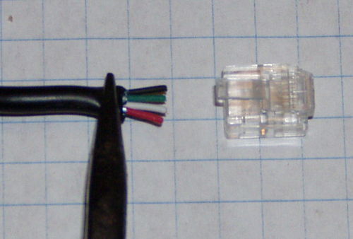
- Spread out the four wires and arrange them in Red, White, Green, Black order.
- Gently flatten the cable with a pair of pliers.
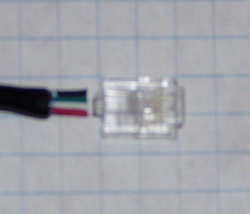
- Evenly trim the wires so they extend approximately 1/4 inch past the jacket.
- Orient the RJ14 connector so the latch tab is up.
- Insert the wires all the way into the RJ14 connector, making sure that the wires are in the right order.
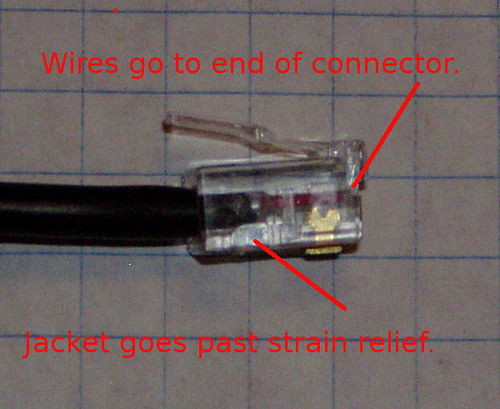
- Inspect the wires and connector with a magnifier. Make sure the outer jacket is past the strain relief and each wire is all the way to the end of the connector.
- If the wires do not extend the full length of the connector, or the jacket does not go past the strain relief, remove the wire and trim a little of the jacket, or shorten the wires.
- Crimp the connector.
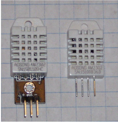
AS2302/DHT22 Temperature and Humidity Sensor
| DHT22 Wiring | |||
|---|---|---|---|
| RJ14 Pin | Color | DHT22 Signal | Description |
| 2 | Black | + | +3.3VDC supply |
| 3 | Red | Out | Pi GPIO |
| 4 | Green | No Connect | Not used |
| 5 | Yellow | - | Digital ground |
Wire: flat telephone wire.
Wire colors are Black, Red, Green, Yellow.
Crimp the RJ14 connector for normal telephone use:
2 Black 3 Red 4 Green 5 Yellow
