Difference between revisions of "Hardware: Hive Interface Board 0.3"
(→Connectors) |
(→Connectors) |
||
| Line 163: | Line 163: | ||
|- | |- | ||
| 3 | | 3 | ||
| − | | I2S | + | | I2S PCM CLK |
|- | |- | ||
| 4 | | 4 | ||
| − | | I2S | + | | I2S PCM FS |
|- | |- | ||
| 5 | | 5 | ||
| − | | I2S | + | | I2S PCM DIN |
|- | |- | ||
| 6 | | 6 | ||
| − | | I2S | + | | I2S PCM DIO |
|- | |- | ||
| 7 | | 7 | ||
Revision as of 04:25, 29 January 2016
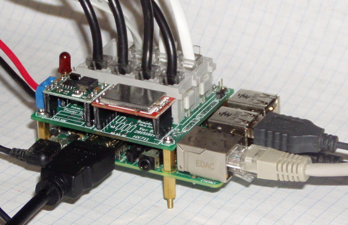
A hive interface board for the Pi is available. The will be part of the Developers Kit hardware. This interim solution is one step further towards the goal of a complete turnkey system.
We hope to have the final version by the end of 2016. See Change: Interface PCB for the proposed design.
Contents
Features
- Plug and Play - all the sensors plug in.
- 12 VDC power supply with battery voltage monitoring
- Supports
- HX711 24 bit ADC and 4 load cells in parallel.
- two DHT22 temperature/humidity sensors.
- TSL2591 Lux sensor
- Rain Gauge
Plug and Play. Telco RJ14 (6P4C) connectors are used for all sensors. These are gold plated, reliable, self wiping, inexpensive, readily available, crimp on with an inexpensive crimping tool, lock in place (latch) and as anyone who has tripped over a phone cord can attest, very strong.
Two different power supplies are optional. These are 12 to 5 volt step down highly efficient switching regulators.
The next step will be to split this board into two boards. One will be a general purpose IO board and contain at least a 4 channel ADC so each load cell will be individually measured instead of being summed, a real time clock, and power supply. The second board will contain the sensor connectors.
The interface board and software works with the A+. B+ and Pi2 models. The board will work with the original A or B if a 26 pin header extension is used although the lack of mounting holes in the original Pi is a problem.
This board was designed on the Pi using the gEDA programs gschem and pcb. The programs, schematic and layout files are included on the latest image.
Connector Wiring
Detailed wiring instructions The Developers Kit uses RJ14 (6p4c) connectors for the sensors. Eventually, the load cells will be supplied with the connector attached. Cables will be provided for the other sensors.
Assembly Instructions
User Guide
Connectors
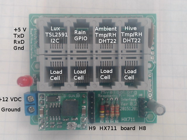
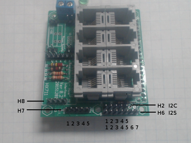
The commonly used connectors on the interface board are shown in Figure 1. Additional optional headers not installed provide access to other GPIO signals for developers.
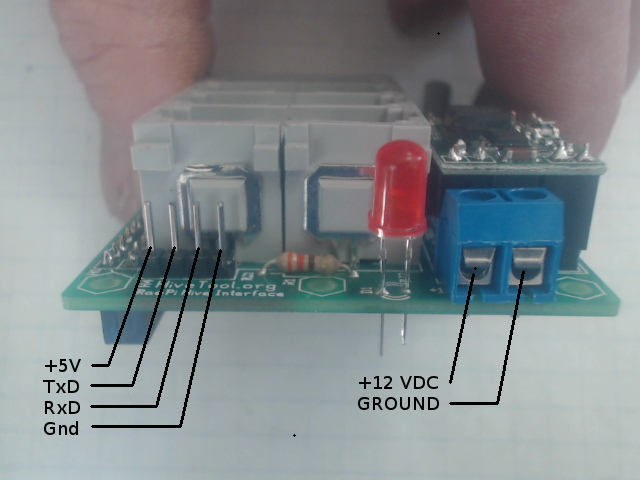
H4 provides access to the serial IO TxD and RxD signals used for the console. A TTL to USB adapter can be used to log into a command line interface from a terminal program such as PuTTY, terminal or minicom. The Pi and interface can be powered through this header.
The top row of RJ14 jacks are for digital sensors. The assignment of sensors is the default HiveTool software setup. These connectors may have unused GPIO signals and can be used for different purposes depending on the software.
The bottom row of RJ14 jacks are analog inputs for load cells. These signals are summed together and read by the high gain channel of the HX711.
Left side of board showing H4 serial IO (console) and power supply connections.
| H4 Serial IO | |
|---|---|
| Pin | Signal |
| 1 | +5 |
| 2 | TxD |
| 3 | RxD |
| 4 | Ground |
Right side of board showing spare SPI, I2C, and I2S connections.
| H7 SPI ver 0.2 | |
|---|---|
| Pin | Signal |
| 1 | +5 |
| 2 | +3.3 |
| 3 | GPIO 11 |
| 4 | GPIO 13 |
| 5 | Ground |
| H7 SPI ver 0.3 | |
|---|---|
| Pin | Signal |
| 1 | +3.3 |
| 2 | SPI0 11 SPI0 CLK |
| 3 | GPIO 13 SPI0 MISO |
| 4 | GPIO 12 SPI0 MOSI |
| 5 | Ground |
| H2 I2C Bus | |
|---|---|
| Pin | Signal |
| 1 | +5 |
| 2 | +3.3 |
| 3 | I2C |
| 4 | I2C |
| 5 | Ground |
| H6 I2S Bus | |
|---|---|
| Pin | Signal |
| 1 | +5 |
| 2 | +3.3 |
| 3 | I2S PCM CLK |
| 4 | I2S PCM FS |
| 5 | I2S PCM DIN |
| 6 | I2S PCM DIO |
| 7 | Ground |


