Difference between revisions of "Hardware: Hive Interface Board 0.3"
(→User Guide) |
(→Connector Wiring) |
||
| Line 30: | Line 30: | ||
==Connector Wiring== | ==Connector Wiring== | ||
| − | The Developers Kit | + | [[Sensor Wiring| Detailed wiring instructions]] |
| + | The Developers Kit uses RJ14 (6p4c) connectors for the sensors. Eventually, the load cells will be supplied with the connector attached. Cables will be provided for the other sensors. | ||
==Assembly Instructions== | ==Assembly Instructions== | ||
Revision as of 07:38, 23 January 2016
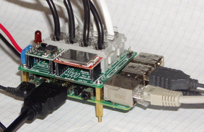
New Developers Kit hardware for the Raspberry Pi platform is undergoing final testing.
This is an interim solution - a step towards the goal of a complete turnkey system.
Features
- Plug and Play - all the sensors plug in.
- 12 VDC power supply with battery voltage monitoring
- Supports
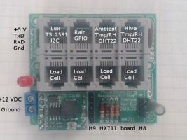
- HX711 24 bit ADC and 4 load cells in parallel.
- two DHT22 temperature/humidity sensors.
- TSL2591 Lux sensor
- Rain Gauge
Plug and Play. Telco RJ14 (6P4C) connectors are used for all sensors. These are gold plated, reliable, self wiping, inexpensive, readily available, crimp on with an inexpensive crimping tool, lock in place (latch) and as anyone who has tripped over a phone cord can attest, very strong.
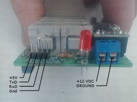
Two different power supplies are optional. These are 12 to 5 volt step down highly efficient switching regulators.
The next step will be to split this board into two boards. One will be a general purpose IO board and contain at least a 4 channel ADC so each load cell will be individually measured instead of being summed, a real time clock, and power supply. The second board will contain the sensor connectors.
The interface board and software works with the A+. B+ and Pi2 models. The board will work with the original A or B if a 26 pin header extension is used although the lack of mounting holes in the original Pi is a problem.
This board was designed on the Pi using the gEDA programs gschem and pcb. The programs, schematic and layout files are included on the latest image.
Connector Wiring
Detailed wiring instructions The Developers Kit uses RJ14 (6p4c) connectors for the sensors. Eventually, the load cells will be supplied with the connector attached. Cables will be provided for the other sensors.


