Difference between revisions of "Interface the HX711 to Pi"
| Line 8: | Line 8: | ||
There are several HX711 boards available. We have been testing the brown boards that have a metal shield. There appear to be two versions of those available. Some only have one chip, some have two. | There are several HX711 boards available. We have been testing the brown boards that have a metal shield. There appear to be two versions of those available. Some only have one chip, some have two. | ||
| + | <br clear=all> | ||
==Prepare the HX711 board== | ==Prepare the HX711 board== | ||
First prepare the HX711 board [[Solder shield and connectors|by soldering the shield and connectors]]. | First prepare the HX711 board [[Solder shield and connectors|by soldering the shield and connectors]]. | ||
| − | + | <br clear=all> | |
==Installation== | ==Installation== | ||
Revision as of 03:54, 29 December 2014
Building a Raspberry based electronic scale using the DCT Electronic HX711 board is as easy as Pi!
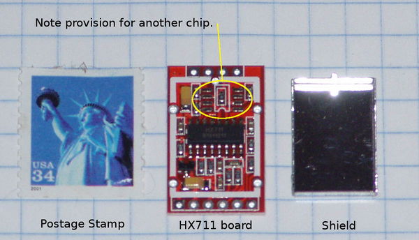
The DCT board comes with a metal shield and two sets of male headers: straight and right angle.
Contents
Required Parts
There are several HX711 boards available. We have been testing the brown boards that have a metal shield. There appear to be two versions of those available. Some only have one chip, some have two.
Prepare the HX711 board
First prepare the HX711 board by soldering the shield and connectors.
Installation
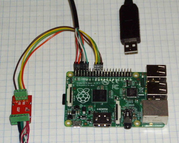
Method 1: Connect HX711 to P1/J8
This will work with all models of the Pi: A, B, A+, B+.
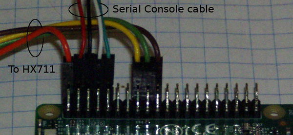
Pins 2, 16, 18, 20 on P1 (Model A and B) or J8 (Model A+ and B+)are used:
| P1/J8 | Pi | HX711 | Color |
|---|---|---|---|
| Pin 2 | +5 | Vcc | Red |
| Pin 16 | GPIO28 | DO/RX | White |
| Pin 18 | GPIO30 | CK/TX | Green |
| Pin 20 | Ground | GND | Black |
#define CLOCK_PIN 24
#define DATA_PIN 23
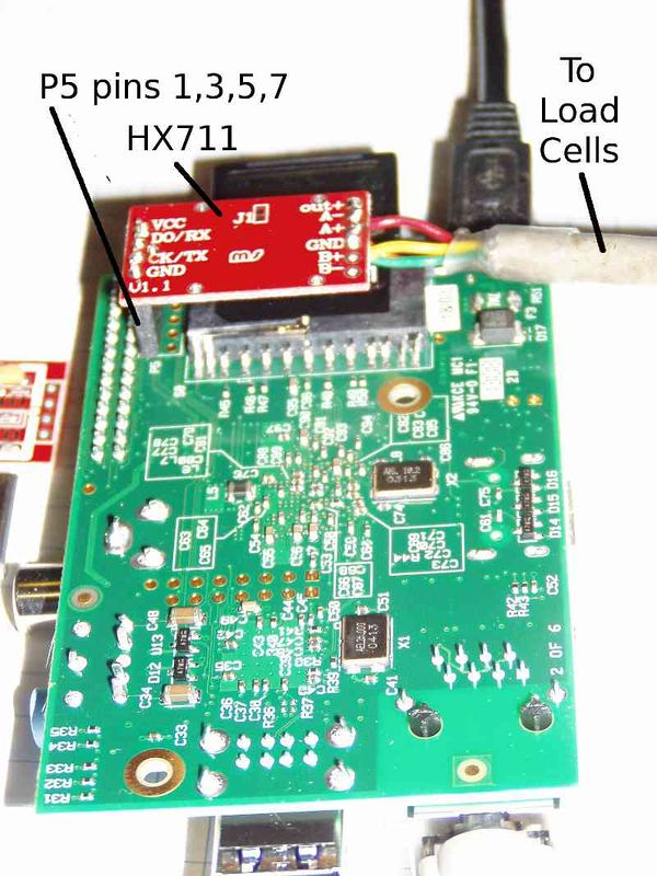
Method 2: Connect HX711 to P5
You will need a 1x4 female header (2.54mm Pitch Straight Single Row PCB Female Pin Headers) and load cells.
- Order the board for $6.99 on Ebay
This one for $2.17 should work, too. - Download the software from gitHub
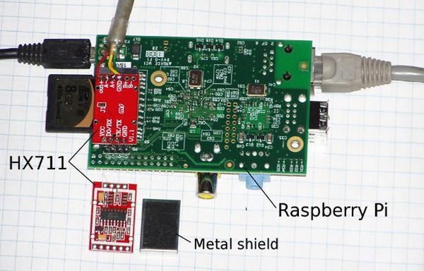
git clone https://github.com/ggurov/hx711 - Solder a 1x4 straight female header in P5 on Pi (bottom side of board) and a 1x4 male header on the DCT board
- Solder the load cells to the DCT board.
- Plug the DTC board into the Pi.
- Change the GPIO pins in hx711.c from 30 and 31 to 28 and 30. This way they are all on one side of P5:
| P5 | Pi | HX711 |
|---|---|---|
| P5-1 | +5 | Vcc |
| P5-3 | GPIO28 | DO/RX |
| P5-5 | GPIO30 | CK/TX |
| P5-7 | Ground | GND |
#define CLOCK_PIN       30
#define DATA_PIN        28
Testing and Calibration
Temperature Compensation
Temperature Sensitivity
From the CZL635 Spec Sheet link below:
Temperature Effect on Span 2.5 g/°C
Temperature Effect on Zero 5 g/°C
From the CZL602X Spec Sheet link below:
Temperature Effect on Span 0.02%F.S/10℃
Temperature Effect on Zero 0.03%F.S/10℃
Full Scale = 50 kg

.02% F.S/10℃
.0002 * 50 kg = .01 kg / 10℃
              = .001 kg / 1℃
              = 1 g/ 1℃
So the CZL602X are 2.5 times more stable than the CZL635
HX711 Spec Sheets
http://hivetool.org/w/images/d/d2/Hx711_english.pdf
