Difference between revisions of "Hardware: PCB Assembly"
(→Install RJ1 and RJ2) |
|||
| Line 17: | Line 17: | ||
==Assembly== | ==Assembly== | ||
| − | === | + | ===40 pin header=== |
1. Insert the 2x20 female header from the bottom side of the board. | 1. Insert the 2x20 female header from the bottom side of the board. | ||
<gallery mode=packed heights=200px> | <gallery mode=packed heights=200px> | ||
| Line 31: | Line 31: | ||
</gallery> | </gallery> | ||
| − | === | + | ===Resistors=== |
{| class="wikitable" | {| class="wikitable" | ||
|- | |- | ||
| Line 67: | Line 67: | ||
</gallery> | </gallery> | ||
| − | === | + | ===Male headers=== |
'''Required''' | '''Required''' | ||
# H8 1x4 and H9 1x6 for the HX711 board. | # H8 1x4 and H9 1x6 for the HX711 board. | ||
| Line 81: | Line 81: | ||
</gallery> | </gallery> | ||
| − | === | + | ===RJ1 and RJ2=== |
Be very careful to check that all the leads are in the holes before you snap it in | Be very careful to check that all the leads are in the holes before you snap it in | ||
| Line 94: | Line 94: | ||
#Install C3 .1 mfd. for rain gauge filter. | #Install C3 .1 mfd. for rain gauge filter. | ||
| − | === | + | ===12 VDC power supply if used.=== |
| Line 109: | Line 109: | ||
==Testing== | ==Testing== | ||
| − | If using Power Supply Option 1, the voltage must be adjusted to 5. | + | If using Power Supply Option 1, the voltage must be adjusted to 5.0 to 5.1 volts before connecting to the Pi or HX711 board. |
Revision as of 04:15, 26 January 2016
Contents
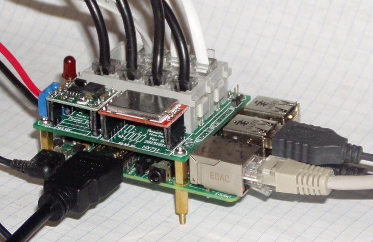
Parts
Mechanical Drawing for RJ connectors.
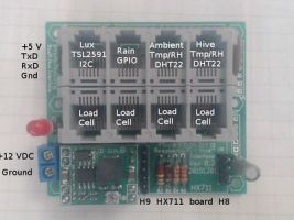
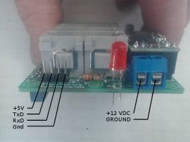
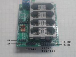
Board Layout
Assembly
40 pin header
1. Insert the 2x20 female header from the bottom side of the board.
- Error creating thumbnail: File missing
1.1 Insert the header from the bottom.
- Error creating thumbnail: File missing
1.2 Solder one pin on each end.
- Error creating thumbnail: File missing
1.3 Check the connector for alignment.
- Error creating thumbnail: File missing
1.4 Melt solder and straighten.
2. Solder the header on the top (component, silk screen) side of the board.
- Error creating thumbnail: File missing
2.1 Solder the rest of the pins.
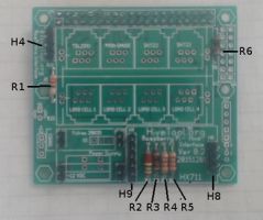
Resistors
| Number | Value (Ohms) | Purpose |
|---|---|---|
| R1 | 330 | Controls brightness of LED |
| R2 | 200K | 12 V monitoring voltage divider |
| R3 | 1K | 12 V monitoring voltage divider |
| R4 | 2.2K | 12 V monitoring Reference voltage divider |
| R5 | 2.2K | 12 V monitoring Reference voltage divider |
| R6 | 1K | Rain gauge input filter |
- Error creating thumbnail: File missing
2.1 Insert the resistors.
Male headers
Required
- H8 1x4 and H9 1x6 for the HX711 board.
Optional
- H4 1x4 for console serial port
- H2 1x5 for I2C
- H6 1x5 for spare GPIO
- H7 1x7 for I2s
- 4 1x2 for 12 V power supply option 1.
RJ1 and RJ2
Be very careful to check that all the leads are in the holes before you snap it in
Install the HX711 board
- Install C1 4.7 mfd. Observe polarity.
- Insert the 1x4 and 1x6 female headers on the make headers.
- Install the HX711 board on the 1x4 and 1x6 female headers.
LED
- Install LED D1.
- Install C3 .1 mfd. for rain gauge filter.
12 VDC power supply if used.
Power Supply Option 1
- Install four 1x2 male headers.
- Install blue screw terminal block.
- Install four 1x2 female headers on the four 1x2 male headers.
- Install the Power Supply board on the four 1x2 female headers.
Power Supply Option 2
- Install Fulree voltage regulator
- Install green spring terminal block.
Testing
If using Power Supply Option 1, the voltage must be adjusted to 5.0 to 5.1 volts before connecting to the Pi or HX711 board.
