Difference between revisions of "Hardware: Sensor Wiring"
(→Load Cells) |
(i) |
||
| Line 18: | Line 18: | ||
#Orient the RJ14 connector so the latch tab is up. | #Orient the RJ14 connector so the latch tab is up. | ||
#Insert the wires all the way into the RJ14 connector, making sure that the wires are in the right order. | #Insert the wires all the way into the RJ14 connector, making sure that the wires are in the right order. | ||
| − | #Inspect the wires and connector. | + | #Inspect the wires and connector with a magnifier. Make sure the outer jacket is past the strain relief and each wire is all the way to the end of the connector. |
| + | #If the wires do not extend the full length of the connector, or the jacket does not go past the strain relief, remove the wire and trim a little of the jacket, or shorten the wires. | ||
#Crimp the connector. | #Crimp the connector. | ||
<br clear=all> | <br clear=all> | ||
Revision as of 03:22, 4 December 2015
The Developers Kit uses RJ14 (6p4c) connectors for most of the sensors. The Registered Jack (RJ) series connectors install using an inexpensive crimping tool.
Load Cells
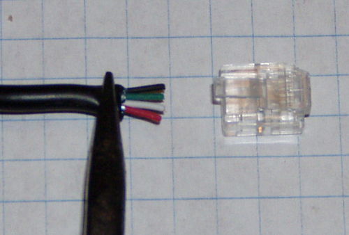
- Remove any heat shrink from the load cell cable.
- Cut off the drain wire.
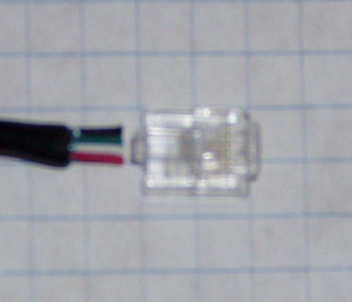
- Spread out the four wires and arrange them in Red, White, Green, Black order.
- Gently flatten the cable with a pair of pliers.
- Evenly trim the wires so they extend approximately 1/4 inch past the jacket.
- Orient the RJ14 connector so the latch tab is up.
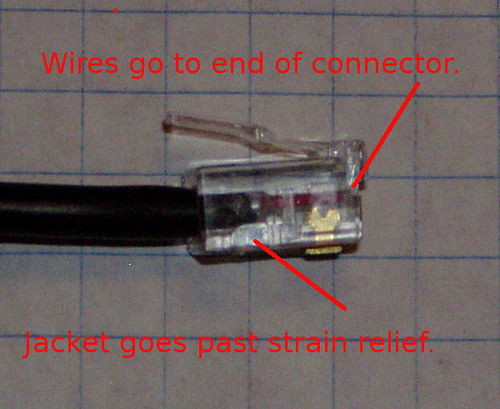
- Insert the wires all the way into the RJ14 connector, making sure that the wires are in the right order.
- Inspect the wires and connector with a magnifier. Make sure the outer jacket is past the strain relief and each wire is all the way to the end of the connector.
- If the wires do not extend the full length of the connector, or the jacket does not go past the strain relief, remove the wire and trim a little of the jacket, or shorten the wires.
- Crimp the connector.
DHT22 Temperature and Humidity Sensor


