Difference between revisions of "Interface the HX711 to Pi"
(→Required Parts) |
|||
| Line 5: | Line 5: | ||
==Required Parts== | ==Required Parts== | ||
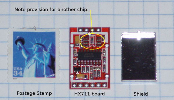
[[File:HX711 wo driver.jpg|thumb|600px|HX711 board without driver chip]] | [[File:HX711 wo driver.jpg|thumb|600px|HX711 board without driver chip]] | ||
| + | [[File:Hx711 version2c.jpg|thumb|300px|Hx711 board with driver chip]] | ||
There are several HX711 boards available. We have been testing the brown boards that have a metal shield. There appear to be two versions of those available. Some only have one chip, some have two. | There are several HX711 boards available. We have been testing the brown boards that have a metal shield. There appear to be two versions of those available. Some only have one chip, some have two. | ||
| Line 11: | Line 12: | ||
<br clear=all> | <br clear=all> | ||
| + | |||
==Installation== | ==Installation== | ||
Revision as of 04:16, 29 December 2014
Building a Raspberry based electronic scale using the DCT Electronic HX711 board is as easy as Pi!
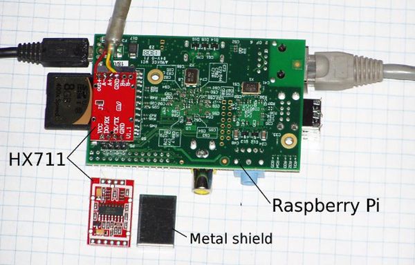
The DCT board comes with a metal shield and two sets of male headers: straight and right angle.
Contents
[hide]Required Parts
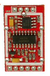
There are several HX711 boards available. We have been testing the brown boards that have a metal shield. There appear to be two versions of those available. Some only have one chip, some have two.
Installation
Method 1: Connect HX711 to P1/J8
This will work with all models of the Pi: A, B, A+, B+.
Prepare the HX711 board
First prepare the HX711 board by soldering the shield and connectors.
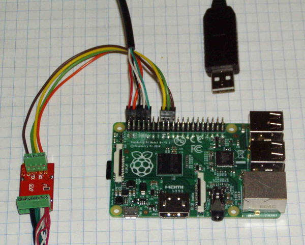
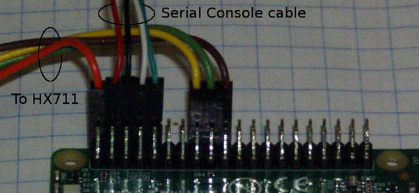
Pins 2, 16, 18, 20 on P1 (Model A and B) or J8 (Model A+ and B+)are used:
| P1/J8 | Pi | HX711 | Color |
|---|---|---|---|
| Pin 2 | +5 | Vcc | Red |
| Pin 16 | GPIO28 | DO/RX | White |
| Pin 18 | GPIO30 | CK/TX | Green |
| Pin 20 | Ground | GND | Black |
#define CLOCK_PIN 24
#define DATA_PIN 23
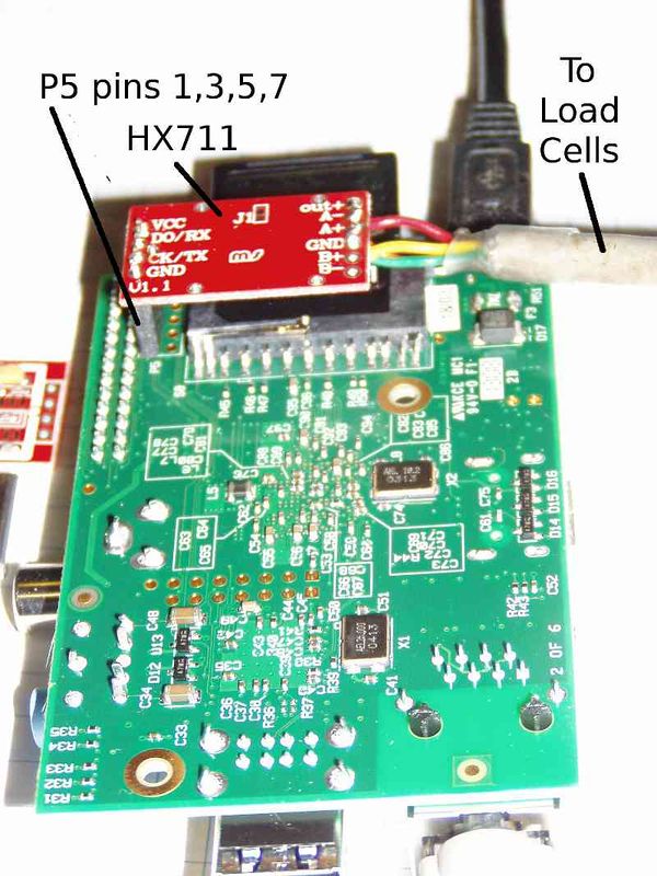
Method 2: Connect HX711 to P5
You will need a 1x4 female header (2.54mm Pitch Straight Single Row PCB Female Pin Headers) and load cells.
- Order the board for $6.99 on Ebay
This one for $2.17 should work, too. - Download the software from gitHub
git clone https://github.com/ggurov/hx711 - Solder a 1x4 straight female header in P5 on Pi (bottom side of board) and a 1x4 male header on the DCT board
- Solder the load cells to the DCT board.
- Plug the DTC board into the Pi.
- Change the GPIO pins in hx711.c from 30 and 31 to 28 and 30. This way they are all on one side of P5:
| P5 | Pi | HX711 |
|---|---|---|
| P5-1 | +5 | Vcc |
| P5-3 | GPIO28 | DO/RX |
| P5-5 | GPIO30 | CK/TX |
| P5-7 | Ground | GND |
#define CLOCK_PIN       30
#define DATA_PIN        28
Testing and Calibration
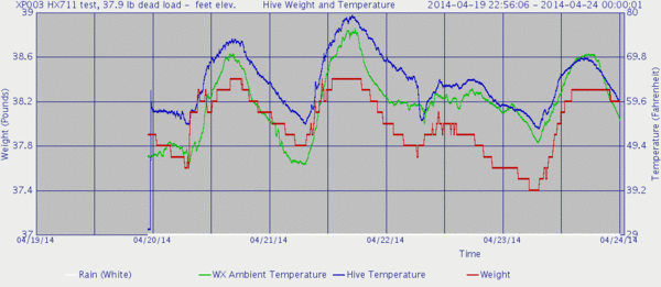
Temperature Compensation
Temperature Sensitivity
From the CZL635 Spec Sheet link below:
Temperature Effect on Span 2.5 g/°C
Temperature Effect on Zero 5 g/°C
From the CZL602X Spec Sheet link below:
Temperature Effect on Span 0.02%F.S/10℃
Temperature Effect on Zero 0.03%F.S/10℃
Full Scale = 50 kg

.02% F.S/10℃
.0002 * 50 kg = .01 kg / 10℃
              = .001 kg / 1℃
              = 1 g/ 1℃
So the CZL602X are 2.5 times more stable than the CZL635
HX711 Spec Sheets
http://hivetool.org/w/images/d/d2/Hx711_english.pdf
