Difference between revisions of "Hardware: Frame Assembly"
| Line 73: | Line 73: | ||
====Set Overload Limits==== | ====Set Overload Limits==== | ||
<br clear=all> | <br clear=all> | ||
| + | |||
| + | ==Solder shield and terminal block connectors on HX711 board.== | ||
| + | |||
| + | '''''This is already done on the developer kits, This step is only necessary if you obtain parts independently.''''' | ||
| + | |||
| + | [[Solder shield and connectors]] on HX711 board. | ||
| + | |||
==Assemble Electronics== | ==Assemble Electronics== | ||
| Line 80: | Line 87: | ||
The electrical connections are made as shown on the block diagram. | The electrical connections are made as shown on the block diagram. | ||
| − | |||
| − | |||
| − | |||
| − | |||
| − | |||
===Connect load cells.=== | ===Connect load cells.=== | ||
Revision as of 15:00, 7 December 2014
Contents
Goals, Features, and Flaws
For design goals, features and flaws, see the Frameless Scale Design
Parts List
For part numbers, suppliers and prices, see the Parts List.
Tools
- Tape Measure
- Pencil
- Layout or speed square
- Hacksaw
- Drill
- 1/4" drill bit
- Center Punch
- File
- 10 mm wrench
- 13 mm open end wrench
- 7/16" [hollow punch]
- Feeler Gauge
Optional tools:
- Metal cutting band saw or cut off saw
- Drill press
- Stationary disk sander
Fabricate Rails
Cut Strut
Cut the strut in 20" lengths. Three can be cut from 5' strut, 6 can be cut from 10 foot lengths. The rails may be slightly less than 20" after losing the width of the saw kerf.
- Mark the strut using a tape measure, If using a hack saw, transfer the marks around the strut using a layout square.
- Carefully cut the strut on the lines, trying to keep as straight and square as possible.
Transfer Layout
Method 1:
- Place a load cell on the top of the rail. It should be about 4 mm (1/4") from the end. NOTE: If it is more than 4 mm from the end you will not be able to tighten the lock nut on the foot and the end cap will not cover the closure strip.
- Using a transfer punch, mark the two 8 mm mounting holes.
- Repeat on the other end.
- Check the punch marks to make sure they are in a straight line.
- Punch the marks deeper using the center punch.
Drill and Debur
Drill the four 1/4 holes in each rail to mount the load cells. Use a file, deburring tool, or stationary disk sander to clean up the ends. They will be covered by the End Caps so they don't have to be perfect. Use a file or deburring tool to debur the holes.
Assemble Rails
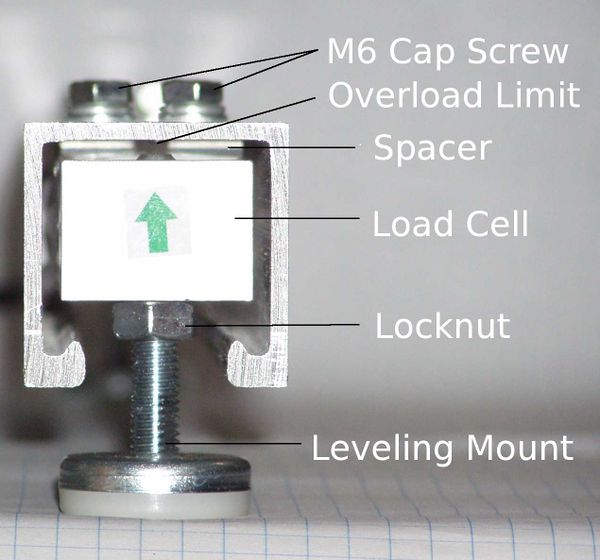
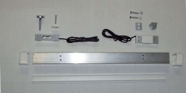
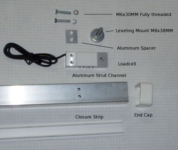
Turn a rail upside down with the open side up. Place a spacer over the holes. Carefully position the load cell over spacer. Align the holes without shifting the spacer.
NOTE: The green arrow on the end of the load cell should point down, toward the top of the rail.
Place a lock washer and flat washer on a M6x30mm bolt. While holding the load cell and spacer in place with one hand, start the bolt in one of the holes. Do the same for the other bolt. Make sure the load cell is centered in the strut and not touching the sides. Tighten the bolts.
Thread an 8 mm hex nut on each leveling foot.
Screw the leveling feet all the way into the load cells. The leveling foot should go all the way through the load cell, but not touch the strut.
Cut Closure Strips
Measure the distance between the leveling feet.
Using the hacksaw, cut the closure strip to fit between the leveling feet. If the strip is cut too long, a rat tailed file or rasp can be use to cut a semicircle in the ends. The closure strips should not contact the threaded portion of the leveling feet.
Punch End Caps
Set Overload Limits
Solder shield and terminal block connectors on HX711 board.
This is already done on the developer kits, This step is only necessary if you obtain parts independently.
Solder shield and connectors on HX711 board.
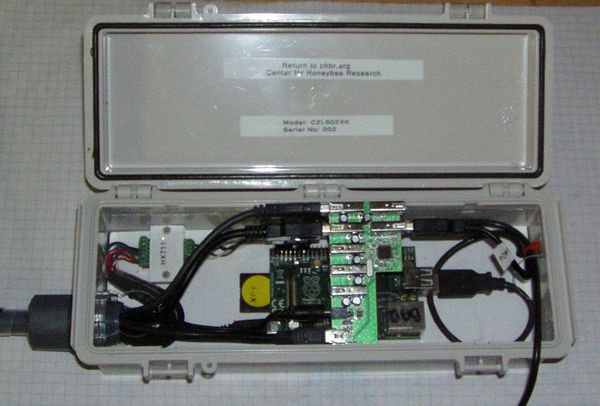
Assemble Electronics
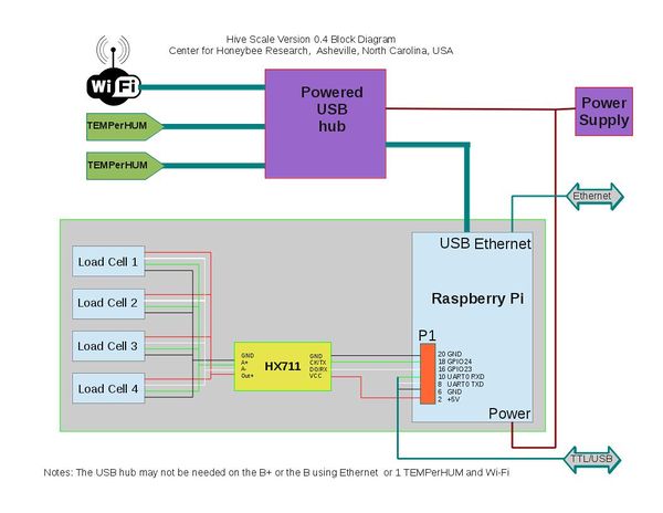
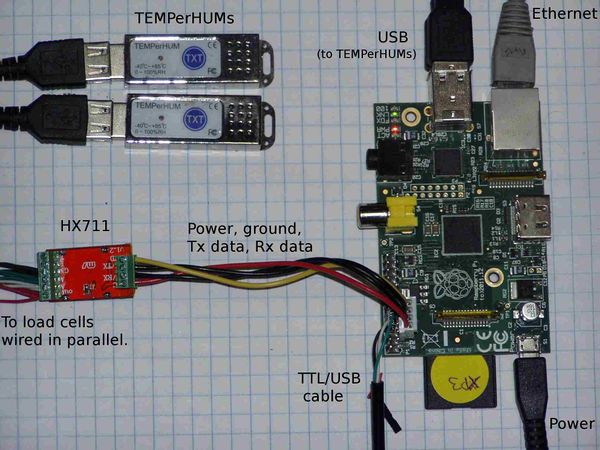
The electrical connections are made as shown on the block diagram.
Connect load cells.
- Each load cell has five wires:
- Red (V+)
- White (A+)
- Green (A-)
- Black (Ground)
- Black (Shield)
Connect power and serial I/O cable to HX711 board.
Connect HX711 serial I/O cable to Pi.
Pins 2, 16, 18, 20 on H1 are used:
Pin 2 +5 Red Pin 16 White Pin 18 Green Pin 20 Ground Black
Connect USB/Serial Console cable to Pi
Pins 4, 6, 8, 10 on H1 are used:
Pin 4 +5 Red Pin 6 Ground Black Pin 8 White Pin 10 Green
Connect Hub, WiFi, and TEMPerHUMs
Testing
If you have not installed the operating system and software on the SD card, load hivetool on the Pi now.
Mount in Enclosure
Several enclosures can be used.

